Setting a match tolerance radius for drone-to-GIS pole reconciliation
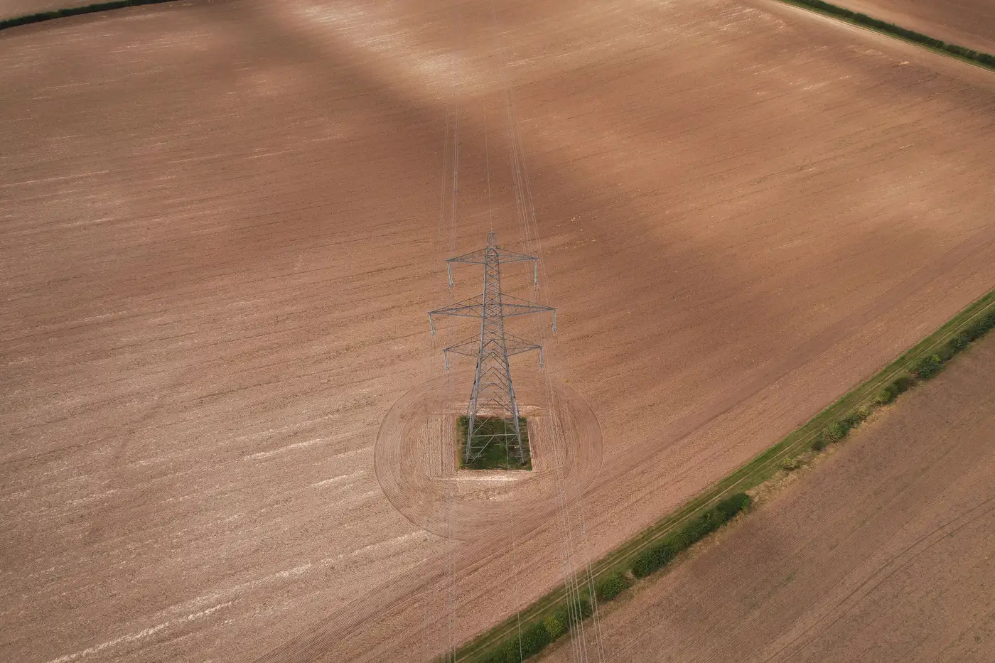
When you run a spatial join between drone-detected pole points and your GIS asset register, the match tolerance radius is the one parameter that decides whether you get a clean reconciliation or a list full of noise. Set it too tight and every pole with a few meters of coordinate drift shows up as missing. Set it too loose and you start pairing a detected pole with the wrong register point entirely, especially in dense line sections or substation yards where structures sit close together.
There's no universal number here. A tolerance that works for a transmission line crossing open farmland will produce garbage in a congested distribution corridor. The right starting point depends on three things: the positional accuracy of your register data, the GNSS accuracy of your imagery collection, and the typical pole spacing on the segment you're reconciling.
Where coordinate drift actually comes from
Most utility GIS registers were built up over decades, migrated between systems, hand-digitized off old plat maps, or captured with consumer-grade GPS during a storm restoration push years back. It's common to find register points sitting 5 to 15 meters off true field position, with no consistent pattern to the error beyond who recorded it and when.
Drone or aerial pole detections, by contrast, inherit the accuracy of the imagery's ground control and GNSS correction. Sub-10cm GSD imagery flown with proper ground control typically puts a detected pole coordinate within a meter or two of its true position. That asymmetry, a register with real uncertainty paired against tight detections, is exactly why the tolerance radius needs to absorb the register's error, not the imagery's.
Picking a starting radius and adjusting for spacing
A reasonable starting point for distribution reconciliation is somewhere between 5 and 10 meters, then tightened or loosened once you've looked at actual spacing in the segment. On a rural tangent line with poles 40-plus meters apart, you can push the radius up toward 15 meters without much risk of pairing the wrong structure. In a tight urban grid or a substation with structures clustered within 10 meters of each other, that same radius pairs everything with everything. You need to drop it down to 3 or 4 meters even if that leaves more unmatched points to review by hand.
Run the join at a couple of radii and compare the match counts before committing to one. A jump from 200 matched poles at 5 meters to 350 at 10 meters tells you the register's drift sits mostly in that 5-10 meter band for this segment. If the count barely moves between 10 and 15 meters, you've already caught the real matches, and anything new at the wider radius is likely a false pair.
False match versus missed pole
Every tolerance choice trades one error type for the other. A false match pairs a detected pole with the wrong register record, often the neighboring structure, and silently corrupts the register with a confident-looking but wrong reconciliation. A missed pole shows up as an unmatched detection, which is annoying but visible. It gets flagged, and someone looks at it.
Because of that asymmetry, most GIS teams lean toward a slightly tighter radius and a longer list of unmatched candidates to review by hand, rather than risk false matches quietly overwriting good register data. Start conservative, widen the radius only in segments where pole spacing clearly supports it, and spot-check a sample of matches at whatever radius you settle on before treating the reconciliation as final.
None of this replaces having an actual detection set to join against in the first place. Grid Asset Inventory runs pole, tower and conductor detection against sub-10cm imagery and hands you a dataset built to reconcile directly against your register, on whatever flight cadence you already fly. If you're setting up this kind of reconciliation workflow, it's worth seeing what that detection output looks like before you build your tolerance logic around it.